Results and Discussion
This is the results & discussion section of the report. The Brittle-Ductile Temperature Graphs show relative toughness, discussion can be found here. The micrographs of the various steels is found here, and the discussion here. This table shows the various permutations and the corresponding experiment number.

Brittle-Ductile Temperature Graphs - Results

Experiment numbers i and ii

Experiment numbers v and vi

Experiment numbers iii and iv

Experiment numbers vii and viii
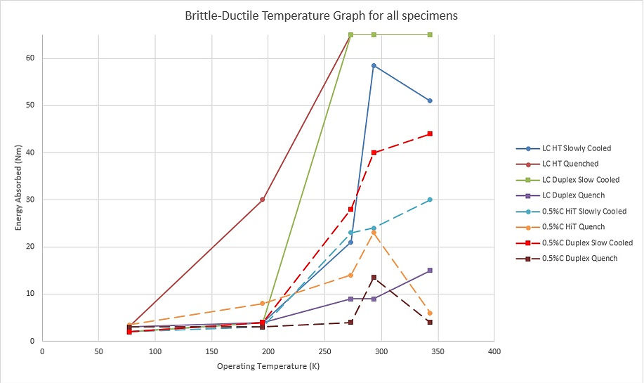
Brittle-Ductile Temperature Graph - Discussion

Ideal Ductile-Brittle Temperature Curve - Reed-Hill
In the case of the experiment numbers ii and iii it can be seen that the values are “saturated” at a maximum of 65Nm. This is the maximum amount of energy that can be transferred by the HBIM – these materials (0.1%C steels, renowned for the ductile characteristics) can likely absorb much more energy and continue to undergo ductile deformation. These materials, the 0.1%C, 1050°C Austenitic quenched steel (ii) and the 0.1C% 800°C Duplex slow cooled steel (iii) exhibited the most ductile behaviour.
On the other end of the spectrum, 0.5%C steels showed extremely brittle behaviour. This is as expected as the higher carbon content is more likely to produce martensite in quench and pearlite in slow cool conditions, both hard but brittle components of a steel’s microstructure. All of the 0.5%C steels showed more brittle behaviour than 0.1%C steels, with the exception of 0.1%C, 800°C Duplex, quenched steel (iv) which appeared extremely brittle. This is likely due to the smaller grain sizes formed with the slow cool causing embrittling behaviour in the low carbon steel.
Generally the materials display behaviour predicted by the Ideal Brittle-Ductile-Temperature graph, with the exception of 3 steels (i, vi and viii) which appear to get weaker with increased heat at 70°C. The most likely explanation for this unusual pattern is experimental anomalies – there are enough small variables beyond the control of the experiment such as inherent weaknesses in the steel specimens which will allow a crack to propagate faster, and can produce a fracture for less energy expended than the average specimen. Therefore, as a further consideration for future research, experimentation should occur with several samples per variable permutation. Having only one data point and not taking several samples and averaging the results is generally frowned upon in experimental science – however due to resource and time restrictions this was not undertaken. This is acceptable for this project to give a rough feel for how brittle or ductile a material is, but more than one sample should certainly be tested.
Therefore the findings of the impact test were as follow: two steels exhibited extremely ductile behaviour within the circumstances (ii and iii). Within the oil refinery where a fire has taken place, ductile material is less likely to fail catastrophically without plastic deformation. Therefore the two steels which were the most ductile could potentially be left in place temporarily – they are less of a risk than particularly the 0.5%C steels which all performed brittle behaviour. It is for this reason that these steels have smaller, more niche uses than use as structural steel.
Furthermore, quenching generally increases the brittle tendencies of the steel. This is likely due to the decreased carbon diffusion rate creating more dislocations between grains which can propagate brittle fracture faster.
There is one exception to this in the 0.1%C, 1050°C Austenitic quenched steel (ii). It is interesting that quenching at this temperature produced an extremely ductile response, whereas quenching the same steel heated to 800°C (iv) created some of the most brittle behaviour encountered in the experiment. It seems from a brittle-ductile viewpoint alone, that quenching is at best a risky response, at worst a way to seriously embrittle structural steel and endanger its structural integrity.
In comparing the steels which have been heated into the austentic and duplex phase regions, the austenitic steels are generally more ductile. This is possibly because in transforming the austenite, the entire microstructure has become austenitic and thus more uniform. This, in essence, “resets” the steel’s microstructure with little to no evidence of the condition of the unheated steel. The duplex region, however, is not hot enough to transform all of the components to austenite. Some proeutectoid ferrite remains, and therefore this must have an embrittling effect on the steel.
The only exception to this is the 0.5%C duplex slow cooled steel (vii). In comparison to the austenitic treated material, the duplex behaves similarly up to 273K, where there is a divergence between the two and the duplex absorbs on average 15Nm more than the austenitic steel. The duplex steel is also the most ductile of the 0.5%C steel, which suggests that brittle pearlite may not be as dominant a factor in this steel. This is a highly interesting result, and will need to be looked at in regard to the material’s microstructure.
Microstructure - Results
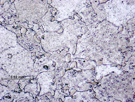
i Low Carbon, Heat Treated to 1050°C, Slow cooled steel


Can see in the right micrograph - clear evidence of dark areas of cementite, possibly pearlite but definitely carbides of some description at the grain boundaries. The condition of very slow cooling has resulted in enhanced carbon diffusion, and so these small areas of localised carbides forming at grain boundaries. This steel is very low in carbon, however there are slightly darker grains within this steel differentiable from the lighter ferrite grains. Upon consultation of the literature and consultation with the project supervisor, the explanation for the presence of these slightly darker grains is not known. It is perhaps a result of the etchant used.
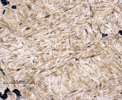
ii Low Carbon, Heat Treated to 1050°C, Quenched steel


Extremely unusual microstructure in this micrograph. There are identifiable Widmanstätten structures which are only made in extreme heat treated materials. These structures are found also in meteorites. A Widmanstatten side plate pattern can be seen in the centre of the right micrograph. These formations often coincide with bainite, suggesting that the cooling was not rapid enough to induce martensite (which is extremely difficult in low carbon plain steel anyway) and has gone into the bainite region. Further analysis of this specimen requires a SEM.
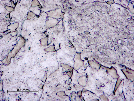
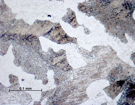
iii Low Carbon, Heat Treated to 800°C, Slow Cooled


This microstructure is similar to i. in many ways – the small areas of dark carbides at the grain boundaries shows evidence of a good rate of carbon diffusion, and also the slightly darker grains which show up under microscope which cannot be resolved.
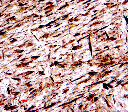
iv Low Carbon, Heat Treated to 800°C, Quenched
There is evidence in the right micrograph of needle-like patterns suggesting martensite within the smaller grains of darkish material. The surrounding material is a ferrite matrix. There are some iron carbides found in the structure, but it they are scarcer than in the as drawn material. An explanation of this microstructure is the austenite formed in the duplex region was transformed rapidly to martensite, and as martensite contains the same carbon content as the parent austenite, the transformation did not diffuse the carbon. The carbides remaining in the structure are likely to be due to incomplete austenitisation and did not transform during heat treatment.
v 0.5C Carbon, Heat Treated to 1050°C, Slow Cooled
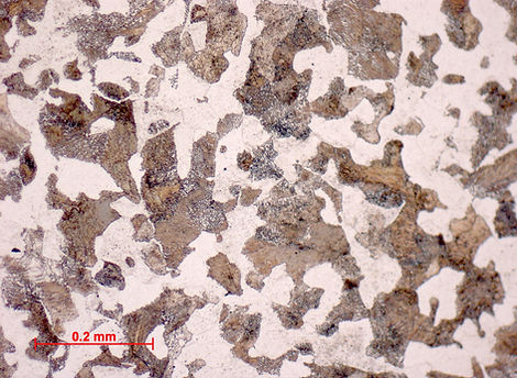
The microstructure here is almost textbook – the white grains of proeutectoid ferrite are clearly visible against the dark lamellar pearlite structure. This is exactly as is expected in a steel containing a reasonable quantity of carbon which is slow-cooled from the austenitic region, allowing a reasonable rate of carbon diffusion. Compare with Callister to the right of this text.

Proeutectoid Ferrite and Pearlite - Callister
vi 0.5C Carbon, Heat Treated to 1050°C, Quenched
There is very strong indication of lath martensite being formed, with a very prominent needle-like structures held within identifiable grains. Clearly the entire microstructure has transformed to austenite, and then martensite in quenching. This was expected with the increased carbon content.
vii 0.5C Carbon, Heat Treated to 760°C, Slow Cooled

This structure here is quite unusual. The darker areas sometimes show lamellar pearlite structures, but there is significant disintegration of pearlite and a “scattering” effect across this surface. This might be simply because the temperature of 760°C to get the steel to the duplex region was not obtained, which may have caused some of the pearlite to transform, and others to partially disintegrate. It is not clear if it is the fault of the furnace or if there is another factor at play, as this material should more resemble sample v. with more structured pearlite.
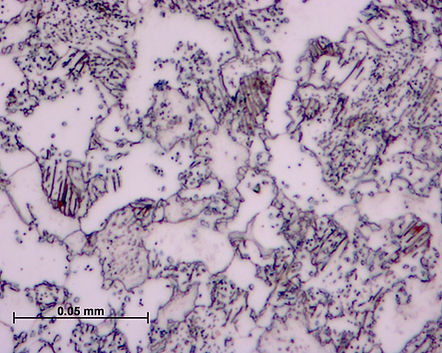
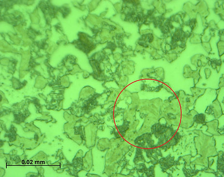
viii 0.5C Carbon, Heat Treated to 760°C, Quenched
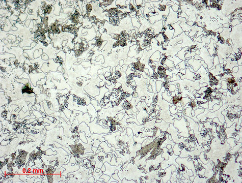
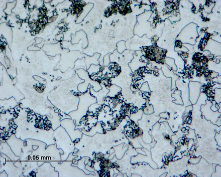
This is another very unusual microstructure. The light grains are ferrite, the dark grains are fine pearlite, and the slightly darker looking grains are difficult to resolve without greater magnification. However, it is likely that this is martensite – there is a faint hint of lath martensite and the tell-tale needle-like structure. An examination with a SEM would reveal whether it was martensite, or possibly even bainite. The below left micrograph shows evidence of decomposed pearlite in the red circle, which may be have occurred in the duplex region. The lower right micrograph shows the needlelike structure which suggests martensite.

Overall
In general, many of the microstructures behaved as expected. Slow cooled material from the austenite region displayed equilibrium conditions and the resulting microstructures are indicative of this. Sample vi, the 0.5%C steel quenched from austenitic region, there is a fantastically clear demonstation of a near-total martensite transformation.
There are some areas which are unresolvable with the current equipment which needs further investigation.
There is some phenomena which needs to be explored in samples i and iii in the light and slightly dark grain appearances. It is uncertain what the difference between these are, and why they showed up with etching and microscope. Perhaps it is over etching which are showing small differences between otherwise similar ferrite grains.
In samples ii and viii, there are some highly uncertain structures caused by the rapid quench which could not be resolved. It is highly recommended that SEM analysis is made as this is vital for the evaluation of the material. Sample ii exhibited very ductile behaviour in Figure 19, the most ductile behaviour over the range of temperatures in fact. This could suggest bainitic transformation as bainite is associated with relatively ductile behaviour. Sample viii, on the other hand, showed extremely brittle behaviour
Additionally, the furnace used should be evaluated to see if it is capable of reaching the temperatures it displays on the monitor, to see what caused the patterns in sample vii, as it is currently consistent with heat treatments to temperatures below the eutectoid point. If the furnace is correct however, there is potentially an extremely interesting process occurring.
However it appears for the vast majority of specimens, their microstructure can be ascertained, and thus, using knowledge of these microstructures, recommendations as to what to do next with the material can be made.
See Conclusions